


Introducing the 'Gen 5' Jafar / XBlast Jafar series modchips!
Gen 5 is the latest iteration of the Jafar modchip. It is an updated, upgraded, open source reproduction of the popular Aladdin XT+4032 XT PLUS2 modchip for the original Microsoft Xbox console.
Initially designed by Kekule of Chimeric Systems, on behalf of Tony Kuberka of TK's Custom Super Modz, the Jafar features the same Lattice CPLD chip as the Aladdin, and utilizes firmware written by Psyko_Chewbacca. It sports several improvements over its budget predecessor:
- 1mb flash memory. With 4 times the memory space compared to the Aladdin, the Jafar is able to offer 2 separate banks for flashing an Xbox BIOS and still leave room for a chip management OS (XBlast Jafar Editions). The Aladdin comes pre-flashed with an Xbox BIOS and has no room for a chip management OS.
- The on-board LED runs off the 3.3v power rail, not the 5v rail like the Aladdin. This means you don't need to pull in a switched 5v feed from elsewhere on a 1.6(b) version motherboard, as the 3.3v rail is switched on all versions of the Xbox.
- LFRAME and D0 are controlled independently, and LFRAME is not held permanently to ground. On a 1.6(b) revision motherboard, holding LFRAME to ground generates additional heat in the MCPX, which could shorten the lifespan of the console. On an Aladdin install, you are required to physically cut the LFRAME trace on the 1.6(b) motherboard in order to avoid that risk. With the Jafar, this is not necessary, since the Jafar only holds the LFRAME to ground whilst booting, then releases it.
- More recent batches of the Aladdin are being released with counterfeit or mislabelled memory chips. These are unable to be flashed by the Xbox console, and must be removed and inserted into an external programmer in order to be flashed. The Jafar can be flashed completely within the console, either using the on-board installed OS, or via a capable utility installed on the Xbox itself.
Early revisions of the Jafar featured a mosfet, but the design was flawed. D0 and LFRAME were tied together, which meant that LFRAME was permanently grounded. As mentioned above, this generates extra heat in the MCPX chip on a 1.6(b) and could shorten it's lifespan significantly.
Taking on board advice from scene member 'Sick Git', Tony Kuberka revised the design to allow D0 and LFRAME to be controlled independently, whilst removing the need for the mosfet altogether. This also means there is no longer a need for installers to deface their 1.6 revision motherboards by cutting the LFRAME trace. He also added in rounded corners to give the chip a more pleasing aesthetic.
The all new "Gen 5" Jafar series modchip is available in 4 versions:

Jafar: In this version, the 1mb flash chip, soldered directly to the circuit board, is divided into two equal 512kb banks. An on board manual switch is used to select between bank 1 and bank 2. Each bank is pre-flashed with XBlast OS, which can be used to flash the selected bank with an Xbox firmware of choice. XBlast OS only sees the selected bank. Once a BIOS is flashed to a bank, it replaces XBlast OS. It is therefore recommended to always leave XBlast OS installed on the second bank, so that if you accidentally mess up the first bank, you can switch to bank 2, boot up XBlast OS again and use it to recover bank 1. This version also has a disable feature. If you connect the disable pad to the Xbox power button, a long press of the power button will boot your console with the Jafar chip disabled.
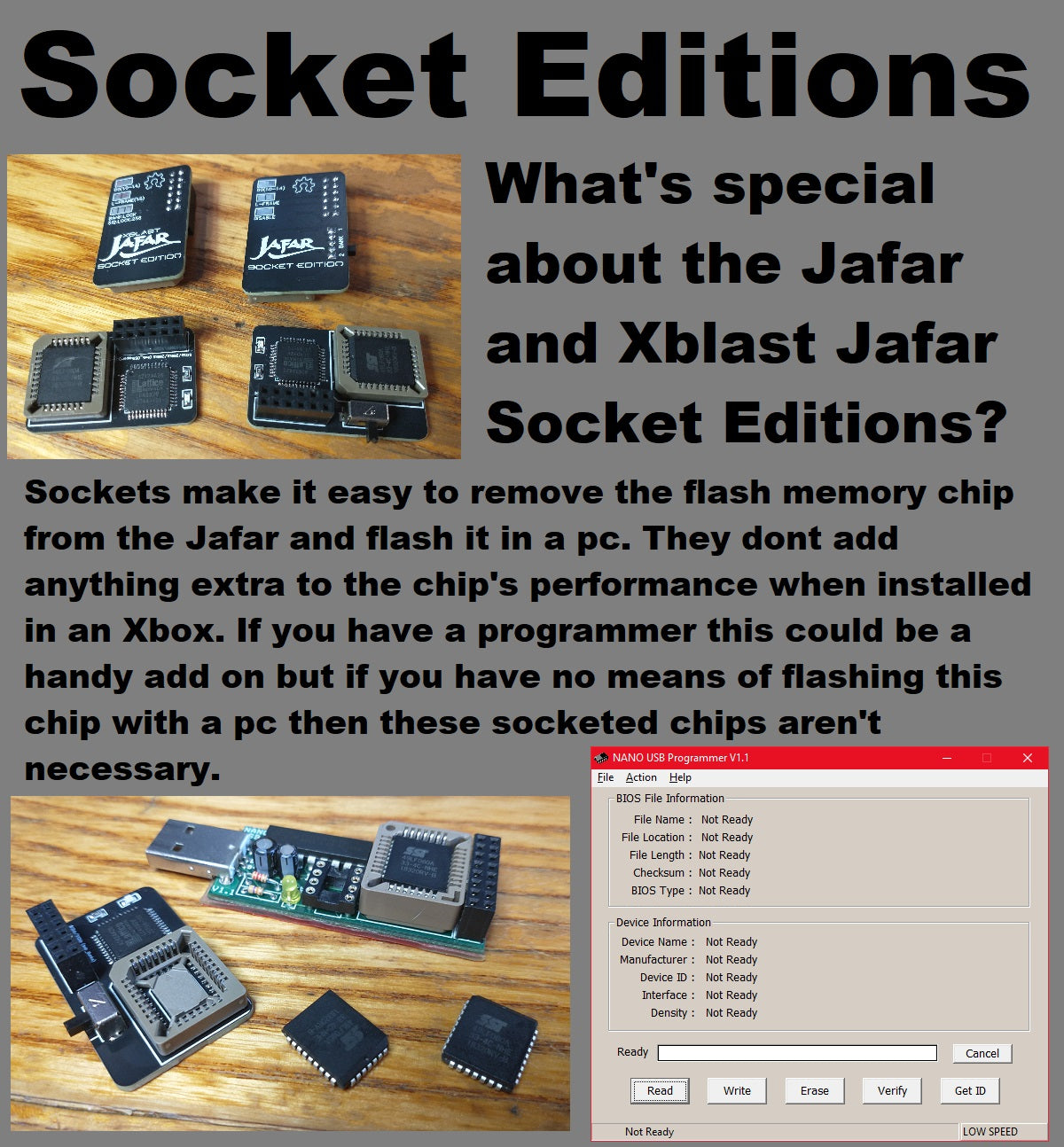
Jafar Socket Edition: This version has the same features as the regular Jafar, but the flash chip is housed in a socket. This makes it easy to remove so that it can be replaced, or connected to a programming device connected to a PC for re-flashing, should the need arise.
XBlast Jafar: This version utilizes XBlast OS as a chip OS to manage the available memory space, providing a 512kb bank and a 256kb bank to which you can flash an Xbox BIOS of your choosing. It also has the ability to lock to a particular bank by soldering some pads on the back. This is useful if you have a failing DVD drive which is known to cause XBlast OS's "Quickboot" feature to stop working. In this version, the 1mb flash chip is soldered directly to the circuit board.
XBlast Jafar Socket Edition: This version has the same features as the regular XBlast Jafar, but the flash chip is housed in a socket. This makes it easy to remove so that it can be replaced, or connected to a programming device connected to a PC for re-flashing, should the need arise.
Disclaimer: XBlast OS is a legal firmware / utility OS. It does not have the capability to circumvent any xbox security measures. I do not provide these chips pre-installed with any BIOS, it is upto you to source a suitable, legal xbox BIOS for your needs.
What's Included?
Each chip will be supplied in an antistatic ESD safe bag with a 2x8 pin header. If you choose to optionally purchase an LPC rebuild QSB, that will be included in the same bag.
Installation Instructions
Please refer to the images at the top of this page.
The chip is supplied with a 2x8 pin header to install into your Xbox motherboard's LPC port if it doesn't already have one.
Please note: The Jafar / XBlast Jafar only uses the first 2x6 pins (closest to the front of the Xbox as you look down on the LPC port from above). I provide a 2x8 header simply because that is the full size of the LPC port on the motherboard, and it future proofs your console should you wish to install a more advanced modchip in future.
Please ensure you install your Jafar / XBlast Jafar modchip onto the correct pins! Failure to do so could damage your chip.
On a 1.0 - 1.4 revision console, you will need to use a small gauge wire (AWG 30 recommended) to connect between the D0 point on the motherboard and the pad labelled "D0" on the Jafar / XBlast Jafar modchip. This allows the chip to control the D0 signal, and gives you the option to boot from the console's onboard TSOP instead of the chip, should you wish. If you have no desire to ever boot from TSOP, and you wish to have your Jafar / XBlast Jafar chip permanently enabled, then instead of soldering the wire to the D0 pad on the chip, you can solder that end to a ground point (such as a screw post or the metal casing). However, it is highly recommended that you solder to the chip, and allow the chip to take control of D0.
On a 1.6(b) console, you will need to first rebuild some of the connections to the LPC port, since Microsoft removed them in these versions. There are 2 ways to achieve this: Using small wires, or using an LPC rebuild QSB. Instructions for both are included in the images on this page.
It is important to note that the most popular LPC rebuild QSB (and the one you will receive if you choose to add it with this product) has a pair of pads incorrectly labelled "D0". Bridging these together will permanently ground the LFRAME signal. However, we do not want this. The LFRAME signal is routed to the LPC port and the Jafar / XBlast Jafar controls it as needed, so do not add a solder bridge to the 2 pads near the "D0" label on the QSB.
Open Source
This project is open source and available to anybody who wishes to have a go at building their own modchip. You can find the repository, including all required source files and instructions, on TK's GitHub.
Special thanks go to Kekule of Chimeric systems, and Psyko_Chewbacca for the initial designs and firmware, and to Tony Kuberka (TK's Custom Super Modz) and Sick Git for the refinements leading to the current version.